A cascade connection of amplifiers is a series connection where the output of one stage is applied to the input of the next stage. Figure below shows a generalized cascaded amplifier connection.

Generalized cascaded amplifier connection
A cascade connection of amplifiers is a series connection where the output of one stage is applied to the input of the next stage. Figure below shows a generalized cascaded amplifier connection.
Generalized cascaded amplifier connection
Many times, the gain of a single-amplifier stage is not sufficient for the intended application. Also, the input or the output impedance of the amplifier at times is not of the correct magnitude for the given application. In such cases, two or more amplifier stages are cascaded to obtain the desired high gain value or meet the impedance requirements.
Common-emitter amplifiers are cascaded to provide power gain.
Common-collector amplifier may be used as the last stage to drive low resistance loads as it has low output resistance. It may be used as a first-stage amplifier by virtue of its high input impedance.
Cascaded amplifier
Cascaded amplifier
Total gain is the product of the gains of the individual amplifiers under loaded conditions. The overall gain (Av) is therefore given by
Where,
Av is the overall voltage gain
Av1 is the voltage gain of stage 1 with input impedance of stage 2 acting on it
Av2 is the voltage gain of stage 2 with input impedance of stage 3 acting on it and its source impedance is the output impedance of stage 1
Av3 is the voltage gain of stage 3 with input impedance of stage 4 acting on it and its source impedance is the output impedance of stage 2
Avn is the voltage gain of stage n with load impedance acting on it and its source impedance is the output impedance of stage (n – 1)
The overall current gain is given by
Where,
Ai is the overall current gain
Av is the overall voltage gain
Zi1 is the input impedance of the stage 1
RL is the load resistance
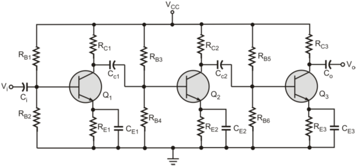
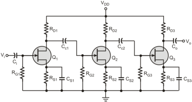
Cascaded three-stage RC-coupled BJT amplifier
Let the h-parameters of the transistor Q1 be hie1, hfe1, hre1 and hoe1; of transistor Q2 be hie2, hfe2, hre2 and hoe2 and that of transistor Q3 be hie3, hfe3, hre3 and hoe3. 
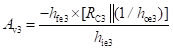
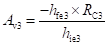
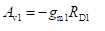
Voltage gain of the third stage is given by
Assuming 1/hoe >> RC3, the equation can be simplified as
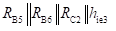
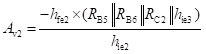
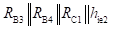
Similarly, the gain for the second stage Av2, assuming 1/hoe2 >>
is given by
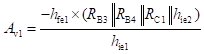
The gain for the first stage Av1, assuming 1/hoe1 >>
is given by
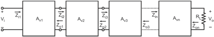
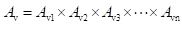
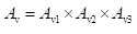
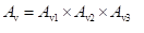
The overall voltage gain Av is given by the product of the voltage gains of the three stages:
The overall input impedance of the amplifier is the same as the input impedance of stage 1 and is given by
Cascaded three-stage RC-coupled JFET amplifier
Gain of the first stage is given by
Where,
RD1 is the drain resistor for stage-1
gm1 is the transconductance value for the stage-1 amplifier
Where, RD3 is the drain resistor for stage-3 gm3 is the transconductance value for the stage-3 amplifier The overall gain Av is given by
The input impedance Zi of the cascaded amplifier is the same as the input impedance of the stage 1.