Common Collector Configuration

  • What is common collector configuration?

    Common-collector (CC) configuration is also referred to as the emitter-follower configuration. Here, the collector terminal is common to both the input and the output sections. It is similar to the common-emitter configuration with the output taken from the emitter terminal rather than the collector terminal. Figures below show the NPN and PNP transistors connected in the CC configuration.

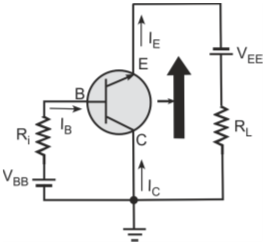
    Common collector configuration for NPN transistor

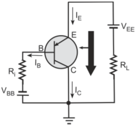
    Common collector configuration for PNP transistor

    CC configuration offers high input impedance and low output impedance. The voltage gain offered by CC configuration is less than unity and the value of current gain is high.

  • Draw the input characteristics of a transistor in CC configuration?

    The input characteristics of CC configuration (Refer to figure below) relate the base current (IB) to the base–collector voltage (VBC) for different values of the emitter–collector voltage (VEC).

    Input characteristics of the CC configuration NPN transistor

  • Draw the output characteristics of a transistor in CC configuration?

    Output characteristics of the CC configuration (refer to figure below) relate the emitter current (IE) to the emitter–collector voltage (VEC) for different values of base current (IB). As we can see from the figure, the output characteristics are similar to that for the CE configuration.

    Output characteristics of the CC configuration

  • Define gamma (γ)?

    Define gamma (γ)?

    where,

  • Why is CC configuration used for buffering and impedance matching applications?

    CC configuration is used for buffering and impedance matching applications as it has high input impedance and low output impedance. Hence, it can drive a low-impedance load from a high-impedance source.

Got a voltage spike of curiosity?

Send your doubts now!