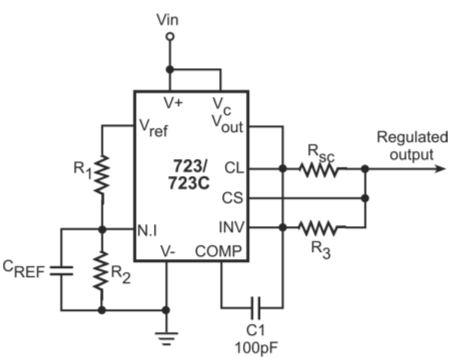
Figure below shows the typical circuit where an external transistor is used to boost the load current delivery capability of a positive output regulator

Use of external transistor to boost current delivery capability of a positive output regulator
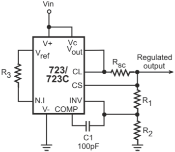
Figure below shows the typical circuit where an external transistor is used to boost the load current delivery capability of a negative output regulator.
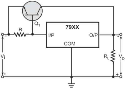
Use of external transistor to boost current delivery capability of a negative output regulator
In both the circuits, as long as VBE (Q1) remains below its cut-in voltage, the regulator functions in its usual manner as if there were no external transistor. As the VBE (Q1) attains the cut-in voltage due to an increasing load current, Q1 conducts and bypasses part of load current through it
The magnitude of load current allowed to go through the regulator equals VBE (cut-in)/R. Rest of the current passes through the external transistor.