Peak Detector Circuit

  • What is a peak detector circuit?

    Peak detector circuit produces a voltage at the output equal to peak amplitude (positive or negative) of the input signal.

  • Draw the circuit of a positive peak detector circuit?

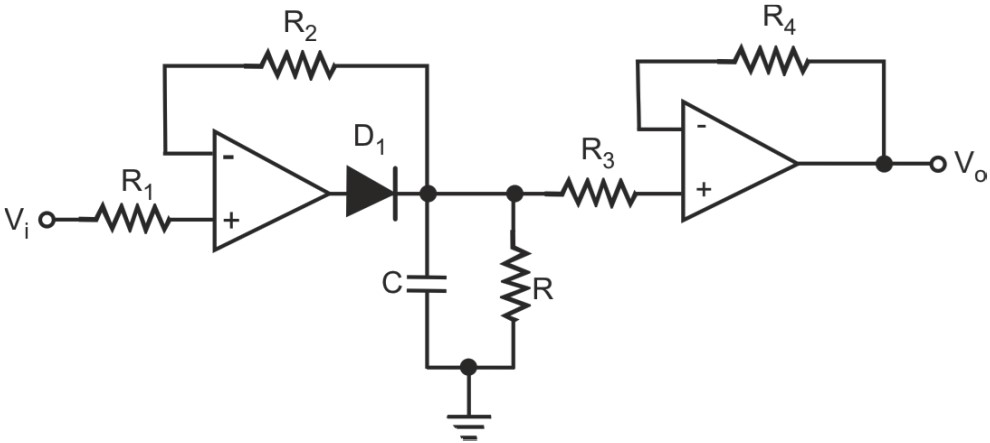
    Figure below shows a positive peak detector circuit. As we can see, it is essentially a clipper circuit with a parallel resistor–capacitor connected at its output. The clipper circuit reproduces the positive half cycles. During this period, the diode is forward-biased. The capacitor rapidly charges to the positive peak from the output of the opamp through the ON resistance of the forward-biased diode. As the input starts decreasing beyond the peak, the diode gets reverse-biased. This isolates the capacitor from the output of the opamp. The capacitor can now discharge only through the resistor (R) connected across it which is chosen to be much larger than the forward-biased diode’s ON resistance. The purpose of this resistor is to allow a discharge path so that the output can respond to decreasing amplitudes of the signal peaks. The buffer circuit connected in front of the parallel resistor–capacitor prevents any discharge of the capacitor due to loading effects of the following circuit.

    Positive peak detector circuit

  • Draw the circuit of a negative peak detector circuit?

    Figure below shows the circuit of a negative peak detector circuit. It is the same as the circuit of positive peak detector circuit except that the polarity of the diode is reversed in this case.

    Negative peak detector circuit

  • How is the R-C time constant chosen for the peak detector circuit?

    The parallel R-C circuit time constant is chosen to be typically 100 times the time period corresponding to the minimum frequency of operation. The R-C time constant also controls the response time i.e. the time needed to respond to a decreasing amplitude. A large R-C time constant would make the response more sluggish. However, reducing the R-C time constant to improve the response time increases the output ripple. Therefore, R-C time constant is chosen as a compromise of the two conflicting requirements.

  • How is the opamp chosen for the peak detector circuit?

    While choosing the right opamp for the peak detector circuit, slew rate is the primary specification that needs to be looked into. The desired slew rate is such that the slew rate limited frequency (function of peak-to-peak output swing and the slew rate), is at least equal to the highest frequency of operation. The peak-to-peak voltage swing at the output of the opamp is equal to
    Vpk – (– VSAT) = (Vpk + VSAT).
    Where,
    Vpk is the maximum peak amplitude of the input signal –VSAT is the maximum negative output voltage of the opamp

Got a voltage spike of curiosity?

Send your doubts now!